Coordinate incident reporting, resource assignment, GIS-based visibility and emergency communications through a structured dispatch workflow.
Becke Telcom Computer-Aided Dispatch (CAD) System is an incident-management and resource-dispatch software platform for control rooms. It gives dispatchers a common workspace for registering events, setting priorities, assigning response units and following field operations through completion. Incident details, locations, responsible personnel and operational updates remain associated with the same case record throughout the response.
The software combines an incident operations workspace, resource management, GIS dispatch, task tracking and supervisory records. Becke Telcom also connects CAD operations with its command and dispatch environment, linking incident tasks to supported telephone, radio, video, intercom, alarm and paging resources. A dispatcher works with the incident in CAD and uses the relevant communication channel without maintaining a separate manual record for each stage of the response.
The system is suited to emergency operations centers, industrial facilities, transport networks, utilities and organizations responsible for multiple sites. Workflows, location references, resource groups and access permissions are configured around the control room's actual operating procedures.
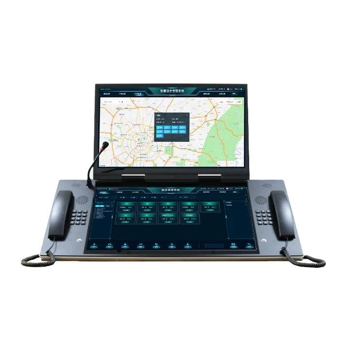
The operations workspace is organized around active incidents rather than individual calls or devices. Incoming reports enter an incident queue, while the selected case displays its location, priority, assigned units and current response state. Dispatchers retain an overview of other active events while handling a particular task.
The incident board presents new, assigned, active and pending cases in a single operational view. Priority, reporting time, incident type and responsible unit provide the context needed to identify urgent work and avoid overlooked reports. Operators filter the queue by status, area or assigned responsibility and open the corresponding record to review its history. Supervisory positions use the same incident information to follow workload and identify cases requiring intervention.
A call-taker registers the reporting source, event category, location, description and initial priority in the CAD record. Reports received from a telephone, radio operator, SOS point or integrated alarm source enter the same case-management process. The record retains its incident reference as notes, supporting information and later observations are added. Where several reports concern one event, operators associate them with the existing case while preserving the individual source details.
Location references include street addresses, facility names, buildings, floors, production areas and equipment identifiers. This is particularly important in industrial sites and transport facilities where a postal address alone does not identify the correct response point.
The case timeline records registration, priority changes, assignments, acknowledgements, status updates and closure actions in sequence. Dispatchers see who made a change and when it occurred, while supervisors review unresolved cases or authorize escalation and reassignment. Notes and dispositions remain attached to the incident instead of being dispersed across operator worksheets. Shift handover therefore starts from the current case state and its recorded actions, not from a reconstruction of earlier phone conversations.
Operational reports draw on incident categories, reporting sources, response milestones and responsible departments. Supervisors use them to review recurring events, delays between assignment and acknowledgement, and unresolved follow-up work without assembling separate spreadsheets after every shift.

The resource view connects people, vehicles and response teams with the incidents that require their attention. GIS provides geographic context for that decision, while CAD maintains the operational assignment and its current status. The two views are linked so an operator moves from an incident location to a suitable resource without losing the case context.
Resources are organized by department, unit, operating area and response capability. The dispatcher sees their current duty and availability status alongside existing assignments, helping prevent a committed team from being treated as unassigned. Resource records also hold the operational identifiers used by the organization's communication directory. When a handset or radio is reassigned, the equipment identity remains separate from the team responsible for the task.
The GIS workspace places incidents and mapped resources in their geographic or facility context. Dispatchers use map layers for stations, roads, site zones, entrances and equipment locations to check access routes and select the correct response area. Location-enabled vehicles and field terminals appear on the map through their connected positioning sources. Their update timestamps help operators distinguish a current location from an older report.
For buildings, tunnels and industrial plants, the location model incorporates floor, section, equipment tag or other site references in addition to outdoor coordinates. Selecting a marker opens the linked incident or resource record, keeping the map connected to the dispatch task rather than functioning as an unrelated monitoring screen.
Dispatchers select a response unit, issue the assignment and monitor its progress from the incident board. The CAD status sequence distinguishes assignment, acknowledgement, travel, arrival, work in progress and completion. Unanswered assignments remain visible for follow-up; another unit or department is added when the incident requires additional capacity or specialist personnel. Multiple teams work under the same incident reference, with each assignment retaining its own responsibility and progress record.

CAD links incident information to the communication resources used during response. The integration provides operators with context for contacting field teams, reviewing incoming alarms and issuing site notifications, while the incident record remains the source of operational task status.
The CAD workspace connects with Becke Telcom SIP communication and dispatch functions for calling control-room extensions, industrial phones, help points and field contacts. Radio users are reached through the supported radio system interface or RoIP gateway, allowing the dispatcher to coordinate telephone and radio resources from the incident context. Individual calling, group communication and conferences are handled through the corresponding communication platform and its configured permissions.
Calls, radio sessions and incident assignments have different operational meanings. CAD records who is responsible for a response and whether the task has been acknowledged; the communication layer supplies the associated contact session and available call information. This separation preserves a clear dispatch history even when several conversations take place during one incident.
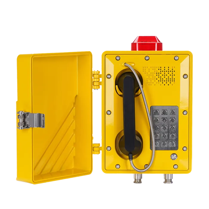
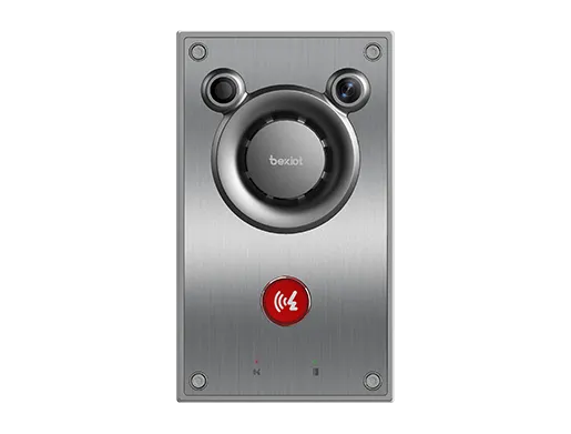
Connected emergency telephones, SOS intercoms and alarm systems deliver source and event information to the control room. A known device identifier links the incoming event to its registered location, making a reported alarm easier to place on the correct facility map. Operators examine the event, record the incident classification and assign the required team. Repeated or related signals stay traceable to their sources rather than obscuring the original report.
CCTV linkage opens the relevant camera view where the video management interface and access permissions are configured. Video supports situational assessment, while the incident board remains responsible for assignments and action history. This allows a dispatcher to review a gate, station platform or plant area without treating the act of opening a video stream as completion of the response.
Incidents that affect a wider area require more than a one-to-one call. The Becke Telcom communication environment provides the connection to supported SIP paging, public address and PAGA resources for distributing instructions to designated zones. Authorized operators select the relevant audience under the site's response procedure. CAD continues to track the teams assigned to investigate, secure or restore the affected area, so the public announcement and field actions remain part of one coordinated incident.
The software architecture separates incident processing, operational data, location services and communication interfaces. This separation is important for multi-position control rooms: several operators work on current incidents while the connected voice, video and alarm systems continue to perform their own communication functions.
Dispatcher workstations access the CAD application services that manage incident records, assignment states, resource directories and user permissions. The data layer stores case details, timeline entries, resource references and authorized operating records. GIS services provide maps, location identifiers and site layers. An incident reference connects these data elements across the operator's workspace without requiring separate records for each screen.
Interface services connect the CAD application with the deployed IP PBX, radio dispatch platform, alarm system, video management system and other operational applications. Integrations are defined by event identifiers, supported commands, returned status fields and access rights. For example, an SOS source passes its device identity and event type, while a communication service supplies the call information available through its interface. CAD uses those inputs to support the incident workflow instead of treating a signaling event as a dispatch decision.
Time synchronization and consistent resource identifiers are part of the interface design. They make it possible to review which event arrived first, which unit was contacted and which operator changed the response status when several connected systems contributed information to the same case.
The system supports a centralized control room as well as deployments serving multiple sites or operating areas. Workstation count, server placement, GIS data, database capacity and interface connectivity are sized around the planned incident load and resource population. Local and regional responsibilities are reflected in operator roles and the incident areas each position is authorized to handle.
Role-based permissions govern incident creation, assignment, priority changes, closure and administration. Access to linked recordings or CCTV footage follows the controls of the respective systems. Backup, power protection, network segmentation and recovery arrangements are incorporated into the deployment design according to the site's continuity requirements; a recovered CAD session does not imply that an interrupted telephone call has remained connected.

An emergency control room handles reports from different sources while several response organizations are active. CAD provides a common incident reference, identifies the duty units responsible for each action and preserves the history of priority changes and transferred assignments. Supervisors follow incidents that require parallel teams, such as rescue, security and site operations, without combining their individual task states into a single misleading completion flag.
At a refinery, power plant or major production site, an event may be identified by process unit, equipment tag or restricted-area reference rather than a street address. The CAD location model directs the report to the appropriate operating area; maintenance, safety and emergency teams receive assignments according to their duties. Connections to industrial phones, alarm sources and site paging support the response while the software retains the action record. Equipment used within hazardous areas must meet the applicable site and equipment protection requirements.
Rail and metro operators use station, platform, tunnel-section and route references to dispatch assistance or maintenance personnel. Ports and logistics centers track incidents around gates, berths, yards and vehicle access points. Utilities organize reports against service regions and asset locations. In each environment, CAD provides continuity between the original incident, the assigned field resource and the final operational disposition, even when the participating teams work from different sites.
Implementation starts with the control room's incident categories, priority rules, operator responsibilities and required response states. Becke Telcom configures the working views, resource groups, location references, authorized actions and reporting fields for the project. The same exercise identifies which alarm, telephone, radio, GIS and video interfaces belong in the operational workflow. This prevents irrelevant data from crowding the incident screen and keeps mandatory actions aligned with site procedures.
Acceptance testing follows an incident from its source to closure. Test cases cover manual reporting, an emergency telephone or alarm input, location matching, unit selection, acknowledgement, escalation and retained case history. GIS records are checked against actual site identifiers, while communication interfaces are checked for the correct source, destination and returned status. Permission tests confirm that call-takers, dispatchers, supervisors and administrators have the intended operating rights.
Failure scenarios are included in the test program: an unavailable field unit, loss of a connected alarm interface, a disconnected workstation, delayed resource acknowledgement and restoration after a service interruption. Operators must be able to recognize what has failed, continue the response under the defined fallback procedure and reconcile records without introducing duplicate assignments or incorrect completion states.
Operator training uses the site's own locations, incident categories and response organizations. Dispatchers practice prioritizing concurrent reports, transferring a case, adding units and closing an incident with a complete disposition. Administrators receive the information needed to maintain resource directories, user permissions, interface settings, backups and recovery procedures. The handover package establishes which CAD services are covered by the deployed system and how operators continue essential coordination during an application or network outage.
For a CAD system proposal, share your required control-room positions, incident types, GIS and facility data, response resources and connected communication systems. Contact Becke Telcom to discuss software configuration, integration and deployment requirements.